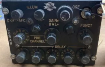
This is a map of ground-based, radio navigation systems for ships and aircraft. Each marker represents the location of a transmitter and antenna. There were several different systems developed in the U.S., Britain, and the Soviet Union. The most widely deployed of these systems was LORAN (short for LOng RAnge Navigation) developed by the United States, indicated by the blue markers on the map below.
Markers for other systems are shown on the map and will be described in a future update of this page. Also, stay tuned for our page on eLORAN.
You can see a list of all of these sites or a Google Map by using these buttons:
Navigation before LORAN
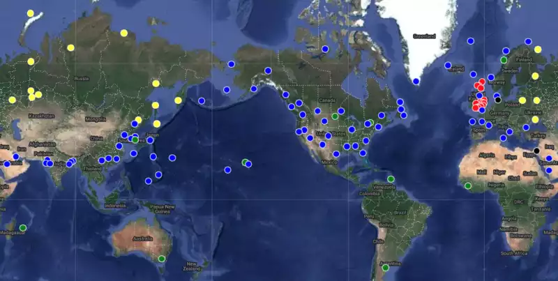
On long-distance polar flights, magnetic compasses could not be trusted to be accurate, so aircraft like the Boeing 707 were equipped with a periscope sextant capability. There was an opening in the cockpit ceiling, rear of the pilot and copilot, that allowed the insertion of the sextant. The opening was normally closed with a valve. To insert the sextant, the valve was opened and air would rush out of the cockpit (with a very loud sound) until the sextant was inserted.
The navigator would take a fix on stars during night flights or the Sun on day flights, and plot their position.
The sextant was also used by ground personnel to calibrate the magnetic compass on large commercial aircraft. The aircraft would be towed to a compass rose—a location at an airport with a painted circle and markers that indicate magnetic directions in 30 degree increments— and the sextant was used to sight objects (buildings, bridges, etc.) that were at known headings. The tug driver towed the aircraft so its nose wheel was placed on compass rose points. Calibrating a mag compass was at least a three-man job, and usually four.
In the late 1960s and early 1970s, that opening in the cockpit ceiling was used for investigations of Clear Air Turbulance (CAT) during selected flights. CAT was responsible for the crash of a Boeing 707, operating as BOAC Flight 911, and using the callsign Speedbird 911, on March 5, 1966. In August of the same year, Braniff Flight 250, which was not a 707, also crashed because of severe turbulence.
Navigating with LORAN
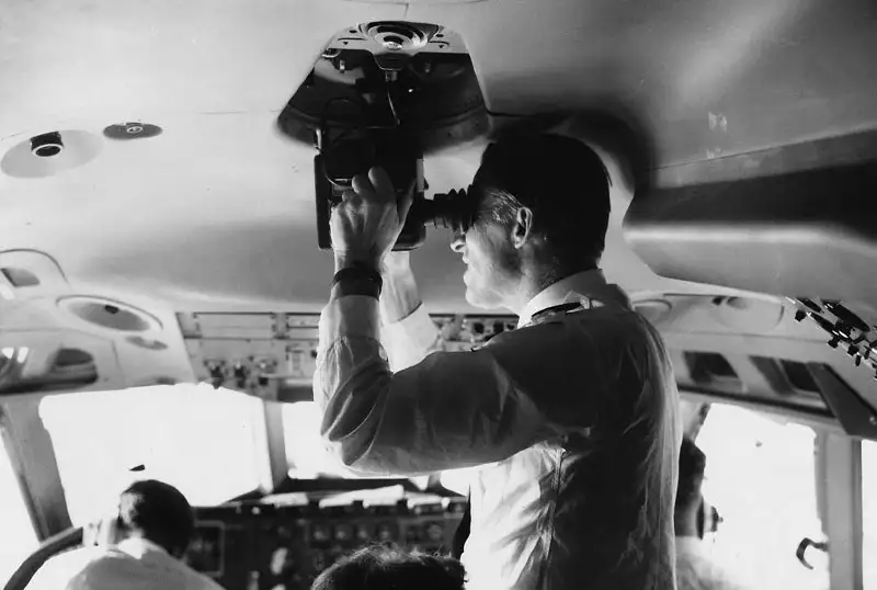
In the early days of LORAN, which was before the widespread use of solid-state logic circuitry, navigating via LORAN (called LORAN A) required that a navigator view a cathode ray tube (CRT) and use calibrated controls to align “pips” on the screen as the diagram below depicts. Charts were then used to determine aircraft position.
On the Boeing 707, the CRT was located in the center console (aka control pedestal) between the pilot and copilot. Given the limited space in a 707 cockpit, the CRT had to be small—it was approxmately 3 inches in diameter. The CRT faced upwards, and in a brightly-lit cockpit a viewing hood was placed over the CRT.
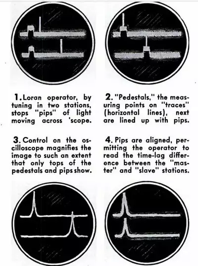
The LORAN control panel was located further forward in the center console. Here's what it looked like: